- 您现在的位置:买卖IC网 > Sheet目录1063 > 10136-6000EC (3M)CONN MDR PLUG 36POS IDC GOLD
�� �
�
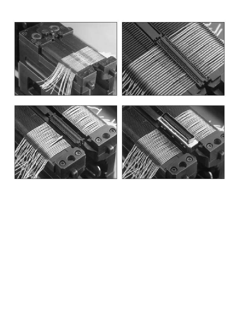
�Figure� 8.� Wires� in� “U”� slot� cover�
�Figure� 10.� Cut� wires�
�8�
�10�
�Figure� 9.� 2nd� cover� on� top� of� wires�
�Figure� 11.� Connector� body�
�9�
�11�
�E.� Repeat� for� the� next� conductor,� except� position� it� to�
�the� rear� and� right.� Place� the� next� wire� in� the� left� slot�
�(adjacent� to� the� first� one),� followed� by� another� wire�
�in� the� right� slot,� etc.,� until� all� conductors� are�
�in� position.� Proceed� to� Step� 5.�
�0.025”� Flat� Ribbon� Cable�
�A.� To� use� the� fixture� unit,� first� remove� the� cable� clamp�
�stop� (B� of� Fig.� 6)� from� the� fixture� unit.� This� is� done�
�so� that� the� flat� cable� may� be� inserted� into� the�
�fixture� unit� without� obstruction.�
�B.� Slide� the� prepared� cable� end� into� the� fixture� slot� so�
�the� first� conductor� is� towards� the� back,� facing�
�the� left� side.�
�C.� Lay� the� conductors� into� the� grooved� wire� holding� slot�
�accordingly� until� all� conductors� are� positioned.�
�Proceed� to� Step� 5.�
�7.�
�8.�
�9.�
�10.�
�11.�
�12.�
�Push� shuttle� block� with� fixture� unit� and� cable�
�subassembly� away� from� the� operator,� back� under�
�the� cutting� unit,� until� it� contacts� the� shuttle� stop.�
�Pull� the� press� handle� down� and� release,� cutting�
�the� wires� (Fig.� 10).�
�Push� platen� back� into� place� using� the� side� bar.�
�Pull� the� shuttle� out.� Placing� one� finger� near� the� center�
�of� the� covers� to� prevent� movement� or� wire� dislocation,�
�remove� the� cut� wires� from� the� fixture� unit.�
�Push� the� release� buttons� on� the� front� of� the� fixture� unit� to�
�allow� placement� of� the� connector� body� over� the� covers�
�(Fig.� 11).� Make� sure� the� alignment� tab� on� the� inside� end�
�of� the� connector� body� is� aligned� with� the� notch� on� the�
�second� cover,� nearest� the� operator.� Push� the� connector�
�body� down� over� the� covers� until� a� slight� “click”� is� heard.�
�Push� shuttle� block,� with� fixture� unit� and� cable�
�5.�
�Pick� up� second� cover� and� rub� the� paper� liner� to� ensure�
�subassembly,� away� from� the� operator� until� it� stops.�
�6.�
�transfer� of� adhesive� to� the� cover.� Remove� the� paper� liner�
�from� the� back� of� the� second� cover� and� place� the� cover�
�(adhesive� side� down)� over� the� wires� and� first� cover,�
�aligning� it� with� the� first� cover’s� guide� pins.� Keep� the�
�notched� end� toward� the� operator.� Press� it� down� on�
�the� first� cover’s� guide� posts� (Fig.� 9).�
�Slide� the� platen� assembly� forward� using� the� side� bar�
�13.�
�14.�
�15.�
�Pull� press� handle� completely� down,� pressing� connector�
�body� onto� the� covers� and� subassembly.�
�Lift� handle� and� pull� shuttle� block� and� assembly�
�toward� the� operator.�
�Completed� assembly� may� now� be� removed�
�from� the� fixture� unit.�
�on� the� operator’s� left� side� to� reveal� the� cutting� unit.�
�4�
�发布紧急采购,3分钟左右您将得到回复。
相关PDF资料
10150-4CZ3PL
CONN MDR PLUG 50POS VERT T/H
10150-72E2PC
CONN MINI-D 50POS R/A PLUG
10150-8000EE
CONN PLUG 50 POS MINI-D
10168-6010EC
CONN MDR PLUG 68POS IDC 26AWG
101A0-4CZ3JL
CONN MINI-D 100POS VERT PLUG
101A0-900APL
CONN MDR PLUG 100POS VERT SLD
101A0-900AVC
CONN MINI-D 100POS EDGE PLUG
102-799-16
CONN PLUG 1.0/2.3 PUSH PULL
相关代理商/技术参数
10136-6000EL
功能描述:D-Sub微型D连接器 36P METAL FACE PLUG 28 AWG RoHS:否 制造商:3M Electronic Solutions Division 位置/触点数量:26 排数:2 安装风格:SMD/SMT 安装角:Right 端接类型:Solder 型式:Female
10136600-101LF
功能描述:VS2 5X6 RH SM 1S/G 制造商:amphenol fci 系列:* 零件状态:在售 标准包装:1,500
10136600-102LF
功能描述:VS2 5X6 RH SM 2S/G 制造商:amphenol fci 系列:* 零件状态:在售 标准包装:336
10136644-0311LF
功能描述:MINITEK PWR 4.2 REC HSG 制造商:amphenol fci 系列:* 零件状态:在售 标准包装:1,000
10136644-0321LF
功能描述:MINITEK PWR 4.2 REC HSG 制造商:amphenol fci 系列:* 零件状态:在售 标准包装:1,000
10136644-0322LF
功能描述:MINITEK PWR 4.2 REC HSG 制造商:amphenol fci 系列:* 零件状态:在售 标准包装:1,000
10136644-0411LF
功能描述:MINITEK PWR 4.2 REC HSG 制造商:amphenol fci 系列:* 零件状态:在售 标准包装:1,000
10136644-0421LF
功能描述:MINITEK PWR 4.2 REC HSG 制造商:amphenol fci 系列:* 零件状态:在售 标准包装:1,000